MCP3208 with RaspberryPi and Python
New version (06/2021)
I renewed this article with more information and a test program for finding adequate parameters. If you miss some information here you can find the original page in the archive [1].
Quick start
To read data from the MCP3208 with Raspberry Pi and Python:
- Enable SPI through the raspi-config command in a terminal or the menu
- Install spidev library for Python, if not already there [2], [3]:
pip3 install spidev - Do the wiring [4]
- Run SimpleMCP3208.py
python3 SimpleMCP3208.py
The program reads values from 0 to 4095, referring to voltages between 0-5V at pin 0. The spi.max_speed_hz = 100kHz works well for source resistance in the range from 1kΩ to 100kΩ. If necessary, you may add a resistor to reduce input current or use an OpAmp to increase current for adequate readings.
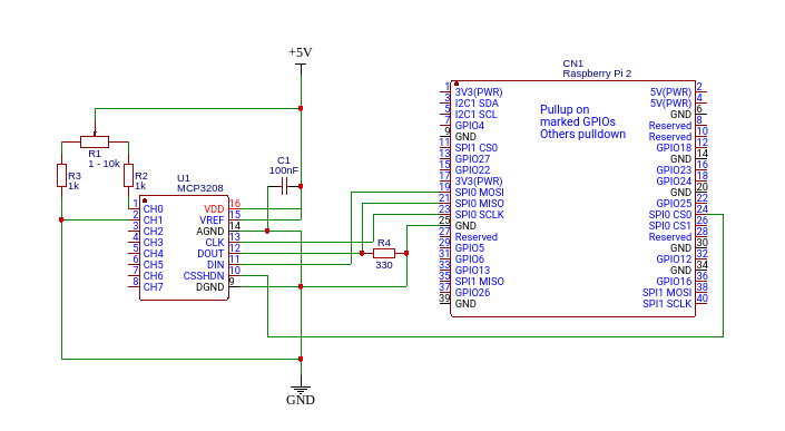 Resistor R4 reduces voltage of DOUT to ~3.2V for RaspberryPI GPIO input on Pin 21, when working with 5V. The capacitor near VDD stabilizes MCP3208 operation.
SimpleMCP3208.py:
Resistor R4 reduces voltage of DOUT to ~3.2V for RaspberryPI GPIO input on Pin 21, when working with 5V. The capacitor near VDD stabilizes MCP3208 operation.
SimpleMCP3208.py:
import spidev


spi = spidev.SpiDev() # Open SPI bus

spi.open(0, 0)

spi.max_speed_hz = 100000


def ReadChannel(channel): # read channel (0-7) from MCP3208

    adc = spi.xfer([6 | (channel & 4) >> 2, (channel & 3) << 6, 0])

    data = ((adc[1] & 15) << 8) + adc[2]

    return data


for i in range(0, 10):

    print(ReadChannel(0))
MCP3208 SPI parameters
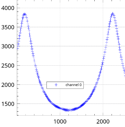
In the code of SimpleMCP3208.py you can see the after opening the device a maximum speed of 100kHz is set. During the development of the polarimeter application [5] a suitable parameter set (max_speed, delay) was found by trial and error.
After these modifications I read reproducible values, yielding smooth curves.
I used this in my Polarimeter project on instructables[10]. The complete wiring diagram for this is available as a public project in easyeda [11].
If you are looking for higher resolution or the I2C protocol, checkout the ADS1115 page [12].
A reader from Mexico (Thanks, Pablo!) pointed out correctly, that in this setting D-out (Pin 12) connected to SPI-0 MISO (Pin 21, BCM 9) is driven with 5V, while GPIOs are specified for 3.3V only. The other connections are not affected as they are driven by the Pi.
I never had an issue with my 2B, but to be safe, you can switch to 3.3V, use a level shifter [13] or add a small resistor (330 Ohms) from D-out to Ground which reduces voltage to ~3.2V.
Links
- MCP3208 on RaspberryPi - until 06/2021
- py-spidev on git hub
- spidev on pypi.org, v.3.5
- Open Source Hardware Lab-Simple
- Open Source Hardware Lab-Parameter testing
- Analogue Sensors On The Raspberry Pi Using An MCP3008
- How to Interface MCP3008 with raspberry Pi
- MCP3208 12-bit Analog-to-Digital Converter (ADC)
- Microchip 3208 Datasheet(pdf)
- AN246 - Driving the Analog Inputs of a SAR A/D Converter (pdf)
- Polarimeter wiring on easyeda
- ADS1115 with RaspberryPi and Python
- level shifter to run higher voltage devices with 3.3V GPIOs